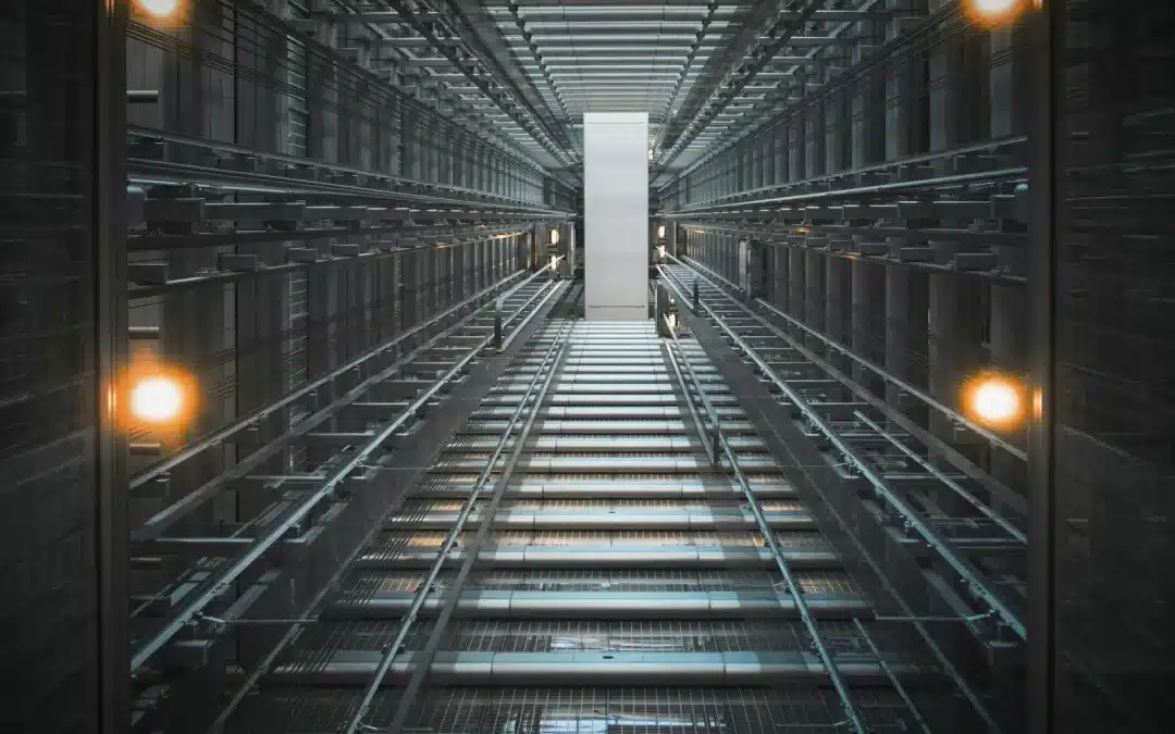
If you carry responsibility for a lift, a diagram only gets you so far. What helps on the ground is knowing what sits inside the shaft, how the parts behave together, and where problems tend to start before they turn into breakdowns. This is our safety-first walk-through of the elevator shaft, from car top to pit, with the maintenance approach we lean on to keep fleets compliant, reliable and steady through the morning rush.
Inside a Lift Shaft: The Direct Answer You Came For
A lift shaft is a vertical, enclosed, fire-rated passage for an elevator. Layouts differ between installations, but when you look inside one you can usually expect to see:
- The lift car and the counterweight running on guide rails inside the shaft
- A traction machine, with electric motor and drive sheave carrying the ropes, or a hydraulic piston where it is a hydraulic elevator
- An overspeed governor linked to emergency brake safety gear
- Landing doors and car doors with door operators that open and close together
- The pit at the bottom, with buffers, sump, ladder, lighting and a pit stop switch
- The overhead at the top, with headroom, beams and, where specified, smoke outlets with metal louvres at the shaft head
- Shaft walls in reinforced concrete, steel, or brick, often with incombustible board panels where added fire resistance is needed
- Ventilation provision to help dissipate heat and limit smoke spread in a fire, in line with the relevant safety regulations
- Electrical controls including the controller, travelling cable, lighting and isolation
Why this matters: these safety systems are designed to work together so passengers arrive where they expect, without drama. Maintained well, they help support compliance underLOLER and theEN 81-20 and EN 81-50 standards. With that picture in mind, let’s begin a practical tour of the parts, and the maintenance that keeps the lift system steady.
Lift Shaft Components That Do The Heavy Lifting
The elevator car travels on guide rails within the elevator shaft. Each component has a job, a failure mode, and a maintenance routine, and in our experience they tend to tell you when something is off if you know where to look.
Lift car and elevator cab
This is the passenger compartment, tied into the controller that manages stops across floors. We often begin inspections with a car top check, because shoe wear, loose fixings, or damaged roller guides tend to show up there first.
Counterweight
It balances the lift car through ropes over the drive sheave. Good balance reduces motor effort and helps smooth out lift operation. We listen for rhythmic thuds, which can point to flat-spotted rollers on the counterweight frame.
Guide rails and rail brackets
These keep the car and counterweight running true. Misalignment often shows up as rub marks and metal dust. We check bracket fixings and rail clip tightness, then clear any swarf that can build up under brackets.
Traction machine
Electric motor, drive sheave and mechanical brakes. In machine-room-less configurations it usually sits at the shaft head. We check brake air gaps, listen for sheave chatter, and review encoder signals in diagnostics.
Ropes or belts
These connect the car and counterweight. Ropes need correct tension, a suitable lubrication regime and regular maintenance. Uneven rope stretch tends to appear as unequal tensions on the hitch plate, so we measure and correct it before nuisance trips start.
Overspeed governor and safety gear
If the car overspeeds, the governor is designed to trip so the emergency brake clamps onto the guide rails. We carry out governor tests at the intervals set for the installation and keep the rope channel clean, since dirt can contribute to false trips.
Doors and door operators
Landing doors and car doors work as a pair. Single, two-panel and single-speed sliding door types are common. Operators use an arm or a linear drive. Many door faults start with debris in the sill or worn rollers, so we clean sills, set close speeds, and confirm interlock engagement.
Control and power
The controller, the drive (often VVVF or regenerative), the travelling cable, and the car top inspection station. We connect diagnostic tools to read error histories, average stops, and door cycle counts. That helps point us to where lift repair should begin and where to schedule parts before they fail.
What’s At The Bottom Of An Elevator Shaft? The Pit Explained
The pit typically contains buffers, sump, ladder and a pit stop switch. It exists to create safe clearances and to absorb energy if something goes wrong.
Buffers. Spring or oil types installed at the bottom to help absorb impact in an emergency. Oil buffer leaks tend to leave tell-tale stains, so we check the oil level and wipe down, which makes any fresh leak obvious on the next visit.
Sump and drainage. Keeps water from pooling, which helps protect concrete and steel components. After heavy rain, we often begin with a torch and check the depth of any standing water, then confirm the pump is live.
Fixed ladder and refuge spaces. These allow engineers safe access inside the shaft. We check rungs are secure and look to ensure refuge clearances are present.
Lighting, receptacle and pit stop switch. These support safe working and lockout during lift maintenance. Before we enter the shaft we prove isolation using the pit stop and test for absence of voltage.
Pit depth varies with elevator type and speed. Designers set clearances for the car under-travel and buffer stroke, and these are engineered per installation rather than taken from a generic table, so you won’t find prescriptive dimensions here.
Safety first: the pit is an enclosed space. Only trained lift engineers should follow the lockout and rescue procedures. If a car halts, passengers are generally advised to wait for rescue rather than attempt self-escape. If you need urgent help, our emergency lift call out covers London, Essex and the South East 24/7.
Safety Mechanisms, Ventilation And Fire Control Inside The Shaft
A lift shaft generally needs ventilation provision, and many designs include smoke outlets with metal louvres at the head. These features are there to help protect life and equipment.
Fire and ventilation points we check:
- Smoke outlets with metal louvres at the shaft head, where fitted, to help control fire spread
- Airflow paths that help dissipate heat from elevator equipment, since excess heat can shorten component life and contribute to nuisance faults
- Ventilation provision consistent with the EN 81-20 and EN 81-50 standards, alongside the local building and fire safety regulations we consult on each project
- Motor chambers and any separate machine room enclosed with non-combustible materials
- Shaft walls in incombustible board on steel frames, or in reinforced concrete or brickwork, chosen to provide fire resistance and sound control
Overspeed and stopping systems:
- The overspeed governor is designed to trigger the mechanical brakes if the car descends too quickly
- Buffers in the pit provide a further layer of protection. Modern elevator shafts typically build in several layers of redundancy to support lift safety
From a compliance point of view, we like to begin by mapping each safety system to a test or a record. That tends to keep your LOLER inspection clean and your risk register short. If you’d like a second set of eyes, ask us to review your latest report. We’ll give you clear options, not pressure.
Lift Shaft Construction And Materials Property Teams Can Rely On
Shaft walls are commonly built in reinforced concrete, steel or incombustible panels. The construction choice shapes programme, acoustic behaviour and maintenance access.
Construction overview:
- A lift shaft is a vertical, enclosed, fire-rated passageway, usually square or rectangular
- Reinforced concrete is common. According to Designing Buildings, precast concrete lift shafts are usually built up to around six storeys and typically start from minimum dimensions of about 1500 mm by 1500 mm, which suits many building cores
- Alternatives include steel framing with incombustible board, or brick and blockwork where the building layout calls for it
- Acoustic control and vibration isolation rely on rail pad selection, machine isolation and careful interfaces with the structure
Material notes we tend to flag during design and lift installation:
- Concrete, steel and brick each need different detailing to maintain fire rating continuity at landings. Door frame interfaces shouldn’t become weak points
- Different materials affect programme and cost. Precast can speed up install but demands precise set-out. Brickwork is slower but can be more adaptable in legacy buildings
- Maintenance access matters. We try to plan rail bracket fixing lines so engineers can reach them without gymnastics, which is the kind of quality workmanship you feel on every service visit
On a recent retrofit, swapping a proposed stud-and-board infill for a small precast module helped resolve acoustic complaints and reduced call outs. A slightly higher up-front cost gave much lower lifetime noise and better lift reliability.
Traction Versus Hydraulic: How System Type Changes The Shaft
Hydraulic elevators use a piston instead of traction ropes. The choice changes what is present in the elevator shaft and how you maintain it.
Traction systems. An electric motor turns a drive sheave, and ropes link the car to a counterweight. Configurations can be machine-room or machine-room-less. Often a good fit for space efficiency and taller travel.
Hydraulic systems. A piston and ram lift the car from the bottom. These often use a shallower pit, with their own overhead, oil management and rescue considerations. Generally suited to low-rise buildings and more modest duty.
Side-by-side comparison:
| Key feature | Traction elevator shaft | Hydraulic elevator shaft |
| Drive systems | Electric motor and drive sheave with ropes | Hydraulic piston and power unit |
| Space | Often more car space thanks to counterweight balance and MRL options | Machine space needed for the power unit. No counterweight present |
| Speed and height | Faster speeds. Suits taller building travel | Generally best for low to mid rise. Moderate speeds |
| Energy | Regenerative drives available. Efficient in commercial duty | Higher start load. Tends to suit lower duty cycles |
| Maintenance | Rope tension and sheave wear, governor tests | Oil condition, seals, cylinder checks, corrosion monitoring |
| Installation | Can install in tight shafts with MRL | Often a simpler install for short travel. Care needed with pit and oil safety |
If you’re weighing system type during lift installation, or planning lift modernisation, we can model lifecycle cost and response patterns. That way you can choose the system that matches your building, not just this year’s budget.
Maintenance Procedures That Keep Shafts Safe And Compliant
Preventive maintenance is one of the most reliable ways to support safe, dependable lift operation across its lifecycle. Here is how we tend to structure routines to protect lift integrity, lift safety and your compliance standards.
Routine checks we perform and why:
- Guide rails. Clean, check clip tightness, verify alignment. Outcome: smoother ride and less wear.
- Ropes. Measure tensions and rope condition, then adjust. Outcome: fewer trips and, typically, longer component life.
- Door operators. Clean sills, set speeds, confirm interlocks. Outcome: doors operating within target timing and, generally, fewer nuisance calls.
- Overspeed governor and emergency brake linkages. Test per schedule. Outcome: documented evidence that the safety systems are ready.
- Ventilation and smoke outlets. Where fitted, confirm metal louvres open and are unobstructed, and test any fans. Outcome: cooler equipment and fewer drive faults.
- Controller diagnostics. Read error logs, average stops and door cycle counts. Outcome: earlier warning for targeted lift repair or lift modernisation.
- Housekeeping. Remove debris inside the shaft, wipe oil from the pit, label isolation points. Outcome: clearer inspections and safer access.
LOLER examination cadence and paperwork:
- We align servicing frequency to duty and environment. Passenger lift servicing visits may be monthly or quarterly depending on usage, and these visits sit alongside, rather than replace, the statutory examination. Goods lift maintenance follows the manufacturer’s guidance and usage.
- Separately, LOLER requires a thorough examination by a competent person, and the HSE sets the usual defaults as at least every 6 months for lifts carrying people and at least every 12 months for goods-only lifts, unless a competent person specifies a different interval in a written scheme of examination.
- We produce signed examination and service records with remedial actions prioritised by risk. Clear, audit-ready and calm.
Safety-first access sequence we follow:
- Begin with isolation and lockout. Prove de-energisation and engage the pit stop switch.
- Begin on the car top. Inspect rollers, shoes, travelling cable saddles and inspection controls.
- Begin door tests. Check landing interlocks, then car door operators.
- Finish in the pit. Buffers, sump, ladder, lighting, and a final isolation check.
Two simple wins we see often:
- A regular deep clean of door sills tends to noticeably cut door-related call outs in busy offices.
- Rope tension equalisation can make a real difference to ride quality and help reduce drive trips. With the right kit, it is usually a quick task.
Summary and key takeaways you can act on now:
- The lift shaft structure is a fire-rated enclosure that holds the lift car, counterweight, guide rails, traction or hydraulic drive, doors, and the safety systems that protect life.
- Safety mechanisms typically include the overspeed governor, emergency brake, buffers, interlocks and, where fitted, smoke outlets with metal louvres. Together they are designed to keep lift operation controlled even when something goes wrong.
- Construction choices such as reinforced concrete, steel frames with incombustible boards, or brickwork affect noise, programme and access. Plan interfaces so fire ratings stay continuous at door frames.
- System type matters. Traction with ropes suits taller buildings and can be more energy efficient. Hydraulic with a piston suits low-rise and simpler installs. Choose with lifecycle in mind, not just install cost.
- Maintenance that begins with isolation, then works from car top to pit, helps keep engineers safe and the shaft clean. Use diagnostics to anticipate failures, and keep ventilation paths open to reduce heat faults.
- Compliance is practical. Align servicing with your maintenance plan and your LOLER thorough examination dates, and document tests for the governor, emergency brakes and door interlocks. That tends to mean fewer breakdowns, better lift reliability and clearer audits.
Lift Engineers London And Essex: How Future Lift Services Helps
Future Lift Services provides independent, multi-brand lift maintenance, repair and modernisation with 24/7 cover. We’re a lift service company Essex teams and London property managers turn to when they want clear advice and steady outcomes.
What you can expect:
- Independent recommendations. No tied brands, just customer-first service and lift transparency.
- 24/7, 365 emergency lift call out across London, Essex and the South East, by qualified lift engineers London based.
- Tailored plans for passenger fleets, goods lifts and platform lifts to help keep you compliant and calm at audit time.
- Free no-obligation surveys, transparent quotes and quality workmanship on every lift repair and lift installation.
Practical next steps:
- Request a survey for a single building or your full portfolio.
- Share recent inspection routines and error histories so we can tune the plan.
- Discuss targeted lift modernisation where it matters most, from door operators to controllers.
We respond quickly, keep you informed, and aim to leave the lift shaft cleaner and safer than we found it.